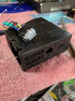
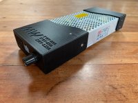
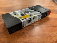
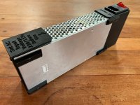
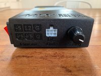
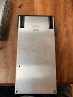
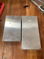
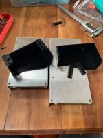
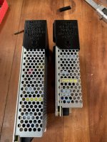
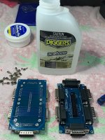
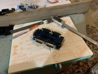
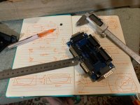
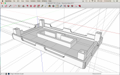
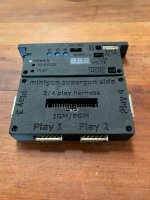
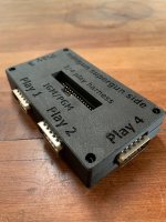
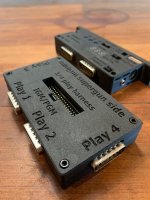
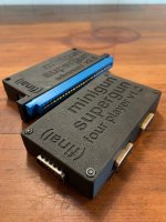
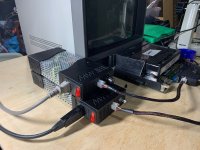
I still wasnt entirely happy with the way the pot was connected to the board (I had hard-soldered it) - it's much better than the preset resistor, but this part needs to be removed for assembly/disassembly - direct soldering felt like bad electrical juju to me,
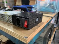
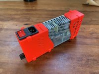
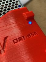
And I wanted to be able to see the LED power indicator on the power supply itself. There is an indicator light on the switch, but it's still useful to see the indicator light on the board sometimes too (it pulses if the power is on but there is no load detected for example)
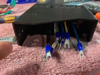
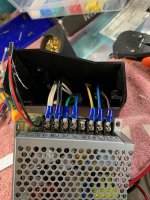
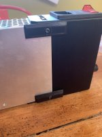
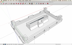
And I still wasnt entirely happy with the cables inside the shell, they were longer than they needed to be.
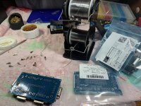
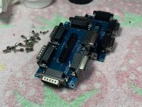
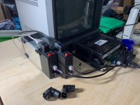
So to fix the preset resistor/pot thing I used a JST XH header. JST XH compact, good mechanically and rated for a decent amount of current. But the pin pattern is 3 in a straight line, and the pin pattern for the preset resistor on the board is three in a triangle. What to do? Luckily there is an unused mounting hole for the preset resistor, making it 2 in a line and one slighty offset.
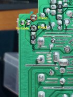
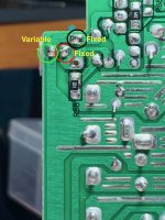
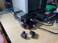
So I was able to make a custom JST XH header to fit the slight offset of one of the variable legs and crimp up the wire ends to make a mechanically sound, electrically safe* solution like this. If I ever need to remove the shell for service I can detatach the pot easily without having to dismantle the power supply and desolder it to get it off
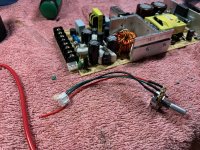
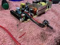
Important note on electrical safety - these wires are 20AWG, and the pot is rated for 1/2 watt. The current is 5V at up to 16A.
It would be possible to wire this as a Rheostat. This would be much more mechanically elegant because then I could use a standard 2 pin header with both the pins in a nice straight line (and I would not have to make a custom 3 pin header). But that would also be an electrical safety disaster. The problem with doing this is that the output of a Rheostat is resistance, it controls the voltage by resisting the current - the current, 5v x 16a = 80watts - and this pot is only rated for 1/2 a watt. I'm not sure if the wires would catch fire before the pot did - and I didnt want to find out. The output of a Variable resistor is voltage, it can control the voltage by measuring the difference - in this case 1v, so 1/2 a watt plenty. Incidently this is why pissy little fixed resistors (teeny tiny potentiometers) can go right into the mains side of a circuit with no problems whatsoever, but the dimmer on on your lights (a Rheostat) is huge and hot an buzzes all the time
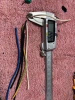
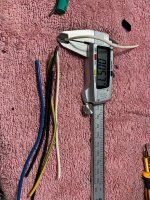
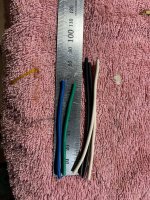
I also cleaned up the other internal wiring - the best lengths that i could find for the raw wires in this shell was as follows
+5 = 85mm cut
GND = 85mm cut
-5 = 65mm cut
+12 = 65mm cut
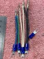
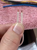
This gives finished wire lengths as follows when the connectors are crimped and the socket is assembled
+5 = 65mm finished
GND = 65mm finished
-5 = 45mm finished
+12 = 45mm finished
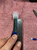
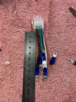
This is about as short as I can make these with 15AWG silicone wire and still be able to assemble the shell easily. It might be possible to make them slightly shorter with 16AWG which would still be in spec, but I didnt have any 16AWG in silicone and more copper is always better where power is concerned
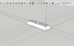
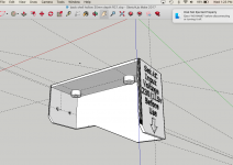
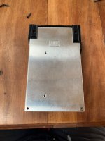
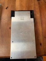
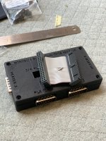
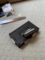
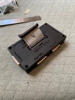
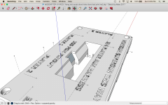
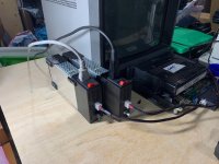
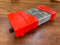
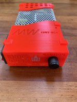
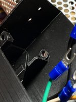
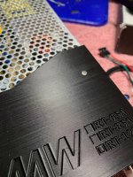
For the LED indicator on the power supply iteslf I used the same trick as I did for the indicator light on the Supergun - 4mm clear plastic rod cut to length and inserted intop a 3.9mm hole in the case. The rod is held in place with (a lot of) friction. One end touches the indicator LED, the other end sits flush with the case. Then the status of the indicator LED is clearly visible without having a big dangerous hole in the case to look through. If you polish the ends of the rod it's possible to get a crystal clear effect, but this is an indicator LED, not some kind of laser light show, so I left it frosted for a gentle glow
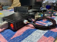
OK, now the power supply really is Done, Done, Done
