You are using an out of date browser. It may not display this or other websites correctly.
You should upgrade or use an alternative browser.
You should upgrade or use an alternative browser.
- Thread starter dewmansnk
- Start date
The power supply was mounted in the most difficult possible way unfortunately. I unscrewed the wood board and mounted the power supply with screws up from the bottom, then reinstalled the wood board. I was hoping someone would eventually make a 3D printed mount that the power supply could snap into. Maybe if I get a 3D printer I will cobble something together.
Thanks for the heads up , it looks clean .The power supply was mounted in the most difficult possible way unfortunately. I unscrewed the wood board and mounted the power supply with screws up from the bottom, then reinstalled the wood board. I was hoping someone would eventually make a 3D printed mount that the power supply could snap into. Maybe if I get a 3D printer I will cobble something together.
Tried to get a couple of these but didn't get a response so I went off and ordered the parts. Here's a dump of the information that I gathered while doing this, hopefully it is useful to someone.
https://github.com/wifiber/AWSD-PS-Interface - Github link which is really everything you need. Take a look at the readme.md file. It contains links to the V5 board and presumably any future updates as well. 3 of the boards are $26.
Actual part numbers from the parts.txt file for the connectors -
https://github.com/wifiber/AWSD-PS-Interface/blob/master/parts.txt
Mouser link for the 8 pin connector (2x4)
https://www.mouser.com/ProductDetail/Molex/39-28-1083?qs=orQbfqMgxgWE1Pu2XYbwgg==
Mouser link for the 12 pin connector (2x6)
https://www.mouser.com/ProductDetail/Molex/39-28-1123?qs=EaMIwIL37xzCyl5w6av%2BuA==
Mouser link for the C&K switch
https://www.mouser.com/ProductDetail/CK/OS102011MA1QN1?qs=WtljUlYws5R6MUgHcLkz4w==
JST / GAM-GEC.com link for the JST connector
https://gam-gec.com/product/bh5p-vh-1/
I skipped the LCD readout.
https://github.com/wifiber/AWSD-PS-Interface - Github link which is really everything you need. Take a look at the readme.md file. It contains links to the V5 board and presumably any future updates as well. 3 of the boards are $26.
Actual part numbers from the parts.txt file for the connectors -
| LCD Voltage Readout | |
| https://www.aliexpress.com/i/32840259666.html?spm=2114.12057483.0.0.206f62fepYHKGu | |
| J1 - Molex MiniFit JR 2x4 0039290083 (gold) 0039281083 (tin) | |
| J3 - Molex MiniFit JR 2x6 0039290123 (gold) 0039281123 (tin) | |
| J4 - JST B5P-VH-FB-B(LF)(SN) | |
| SW1 - C&K OS102011MA1QN1 |
Mouser link for the 8 pin connector (2x4)
https://www.mouser.com/ProductDetail/Molex/39-28-1083?qs=orQbfqMgxgWE1Pu2XYbwgg==
Mouser link for the 12 pin connector (2x6)
https://www.mouser.com/ProductDetail/Molex/39-28-1123?qs=EaMIwIL37xzCyl5w6av%2BuA==
Mouser link for the C&K switch
https://www.mouser.com/ProductDetail/CK/OS102011MA1QN1?qs=WtljUlYws5R6MUgHcLkz4w==
JST / GAM-GEC.com link for the JST connector
https://gam-gec.com/product/bh5p-vh-1/
I skipped the LCD readout.
Sorry about that, I saw you reached out and should have responded. My bench is not really accessible at the moment, so I am pausing on building these for a bit. Looks like you were able to source the parts so hopefully you got all setup. I think @Lemony Vengeance did a batch as well, so that might be another option.
Lemony Vengeance
Champion
I have a bunch that will be ready once the voltmeters get hereSorry about that, I saw you reached out and should have responded. My bench is not really accessible at the moment, so I am pausing on building these for a bit. Looks like you were able to source the parts so hopefully you got all setup. I think @Lemony Vengeance did a batch as well, so that might be another option.
")
Super stokedI have a bunch that will be ready once the voltmeters get here
Did a quick and easy mount using the stock Wei-Ya bracket. I flipped it around so I could adjust the voltage pots from the left side.
Use M4X5mm or 6mm screws so you don’t hit the bottom of the power supply pcb inside.
Use M4X5mm or 6mm screws so you don’t hit the bottom of the power supply pcb inside.
Attachments


looks good tony. i cant wait to try it out once my chassis comes back
Looks great ! nice job.
I ended getting these feet. The good news is they’re very cheap. The not so good is that they’re meant to be installed with the power supply in horizontal position… I didn’t realize this until I got themThe data sheet for the Mean Well QP-150-3A shows optional mounting feet. Searching around, it looks like the part number is MHS012.

I ended just bending them so the feet themselves were flat instead of L-shaped. Here’s the results when installed.


BTW, the interface works like a charm! Great job!!
@dewmansnk whats the proper screw or bolt to go into the ground socket
@dewmansnk whats the proper screw or bolt to go into the ground socket
Its a M4 sized hole, so a M4 screw and nut should work. Looks like @notsonic beat me to it, he has the right idea.
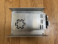
Hi everyone!Fans arrived, did a little more cutting on the case to removed the internal/lame-airflow restricting grill.


Sorry to derail this thread, but would you know if there is any chance I can internally swap out the fan for a GELID SILENT 6 FN-SX06-38 ?
thanks a lot for any pointers
Edit : tested, and too thick to fit inside as is.
Last edited:
Wondering if someone can help me real quick,
I tried to install the voltage meter and switch on the pcb. When i power on i get 0.00 reading.
Not sure if i wire it wrong or maybe i have to solder in Jp2 and Jp3 in the back?
I tried to install the voltage meter and switch on the pcb. When i power on i get 0.00 reading.
Not sure if i wire it wrong or maybe i have to solder in Jp2 and Jp3 in the back?


