What's new
added to the previous file, attached (ft_ep1_27c4096.bin)

appears worst when trying in mame?
It's actually slightly better dump but still repeated , does your programmer detect pins? if not can you try another eprom reader?
There's other tricks to try such as heat / cold to try and get a good read....
 
It's actually slightly better dump but still repeated , does your programmer detect pins? if not can you try another eprom reader?
There's other tricks to try such as heat / cold to try and get a good read....

I read it with gq4x + adapter.

Here it is read with the TL866 which yes did detected pins:

APP Version : 11.80 Model : TL866II Plus
Device : M27C4002 @DIP40
Pins Detected Passed!
ID: 0x0020 0044......OK!
Reading FLASH ...Succeeded. Time : 3609ms
Read Finished!

The files are different and it "runs" much better in mame but still no go I believe?
 

Attachments

  • fairy_tales.zip
    172.9 KB · Views: 94
As you say, this dump is also suspect..
At this point for me, it's hard to tell, both are missing some data but it seems to be there in the other dump?! :)
Does it also verify OK if you take the chip out / put it back in?

Maybe it's also worth trying the heat trick, to see if the data changes ...?
 
in mame, when you get to "Call the person in charge", hit red-green-red-green (z,x,z,x) and that screen will go away and you can "play it".

"red and green" are OK and CANCEL:

CTRL: From the 6th pin: LEFT, RIGHT, OK, CANCEL, GND. Active low.

Wire some buttons and see if that works ?!

So after building a very high tech control panel, it's still on the "Call the person in charge" screen when pressing the buttons in alternating order multiple times. Fair chance I've messed up something, but if OK and CANCEL are adjacent to GROUND (and I confirmed the right most pin is ground) this should be correct.
1710712980121.jpeg
 
  • COUNT: 7th pin triggers test mode, active low.
There’s a switch test in there that could help confirm your buttons if you can actually get in !
 
  • COUNT: 7th pin triggers test mode, active low.
There’s a switch test in there that could help confirm your buttons if you can actually get in !

Don't suppose anyone knows the hardware dip to get into the test? Pulling the 7th from the right pin low isn't doing anything.
 
Ok since I've never done this, how much heat? how long? Thanks!
You want to warm it up, but not cook it...
So maybe something like a hairdryer or a heat gun / air station on very low for a minute should do the trick.
 
:(

From furtek’s video (he’s the one who made the dev wiki)
View: https://m.youtube.com/watch?v=OuGmNmOLhJo
, he’s saying none of the dips are used…

While I can curse in several languages, french isn't my strong suit (title says it has english subs, but they're not working for me). Big thing I noticed when I previously viewed this video is that when he boots up, it's not mirrored like what I'm seeing and it goes straight into the attract mode. I can't tell what he has setup with the bread board, but it looks like he has things wired into the printer IO on the motherboard. That's my concern, that there's a check for the printer. Not sure how I can go about fooling the board into thinking it has a printer, but I suspect that's what he's doing.

Auction for the manual ends tomorrow, if I win I'll scan and translate everything & share a PDF.
1710762948030.png
 
Last edited:
like a hairdryer or a heat gun / air station on very low for a minute should do the trick.

I:\roms\fairy_tales\fairy_tales>fc /b ft_ep1_M27C4002@tl866.BIN M27C4002HOT.BIN
Comparing files ft_ep1_M27C4002@tl866.BIN and M27C4002HOT.BIN
FC: no differences encountered

while there I tried freeze spray

I:\roms\fairy_tales\fairy_tales>fc /b M27C4002HOT.BIN M27C4002COLD.BIN
Comparing files M27C4002HOT.BIN and M27C4002COLD.BIN
FC: no differences encountered


guess that's it? the fact that the roms are socketed probably means somebody tried to burn new roms cause EP1 was already bad?


Edit: I have redumped all with the TL866 and if I replace the bad EP1 with the one from popeye, it is actually much better then before (aka text is properly displayed) so consider this dump "good"
except the EP1, which now gives this if the EP1 from popeye is replaced:

prog.png
 

Attachments

  • fairy_tales.zip
    530.4 KB · Views: 96
Last edited:
Love the cartridge dumping discussions, will need to see which ones from my pile aren't dumped once I can confirm they're working.

The current issue: bypassing the printer check.

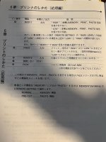
  • PRT2: Printer remote. See printer's manual. Both BUSY lines can be tied together ?
  • PRT1: Printer remote also (needed or just for backup ?). The BUSY line can be tied with the 2 other ones ?
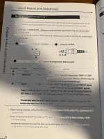
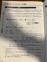
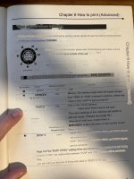
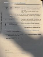
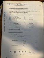
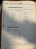
To pass the printer check before attract mode, put the busy lines low for approx. 20ms after the end of each transmission on REMOTE (DIN pin 6).

Trying to figure out what is meant by this, going to see if I can track down a Mitsubishi CP710 printer manual.
 
Printer manual is a think boy, not sure there's any information in it relevant to bypassing the printer check (DIN8 pinout) but I'll check. Not going to bother scanning and translating the whole thing.

1711039615749.jpeg
 
And found it, starting at page 106. At work so just doing a quick photo and Google translate.

Page 106:
IMG_1785 eng.jpegIMG_1785.jpeg

Page 107:
IMG_1786 eng.jpegIMG_1786.jpeg

Page 108:
IMG_1789 eng.jpegIMG_1789.jpeg

Page 109:
IMG_1787 eng.jpegIMG_1787.jpeg
 
Last edited:
So based on this, I have the following...

1711042793612.png

• PRT2: Printer remote. See printer's manual. Both BUSY lines can be tied together ?
• PRT1: Printer remote also (needed or just for backup ?). The BUSY line can be tied with the 2 other ones ?
To pass the printer check before attract mode, put the busy lines low for approx 20ms after the end of each transmission on REMOTE (DIN pin 6).

So shorting pin 3 on the phono jack along with pins 3 & 4 on the din-8 for 20ms when pin 6 sends a transmission. This is going to require a custom circuit... arduino or similar microcontroller looking for data on pin 6 and sending back a busy signal. This must be what's on the bread board in Furrtek's video. Wish I had their design handy. If anyone has any thoughts on this, please chime in. Page 109 has some of the TTL examples.
 
Last edited:
Hello,

All I have left from this is the Neoprint board (that I'm way too lazy to set back up), and a vague souvenir of what the breadboard circuit did.
It was fully analog, possibly a CD4528 or one or two NE555 wired as monostables. The activity on the data pin was triggering one of them, and after a fixed delay, another one sent out the busy pulse to make the system believe the printer was working.

IIRC that just made the system pass the self-test and go into attract mode. After a few steps into the process of setting up the printout, it gave a "call the person in charge" message.

If anyone wants to dive in the code with MAME to guess what it's expecting, printer I/O is done via regs between 0x600000 and 0x60000f.

I believe a smarter printer simulator based on an Arduino or similar is the way to go :)
 
I believe a smarter printer simulator based on an Arduino or similar is the way to go :)

Thanks for chiming in! Yeah I'm thinking that if I can get an Arduino setup I can record the requests coming in from the Neo Print and hopefully figure out what it wants as a response. With page 109 of the printer manual we have a list of commands. It looks like it's just 8 bit binary TTL.

Sourcing a few bits and pieces, like a mini-din 8 break out board.
 
Various mini-din 8 breakout options (ordered the PCBs for the green ones only to find I already had the red). Looks like my cable is a bit bent... will check continuity but I may need to find a new one or rebuild this one.
1711214387183.jpeg
 
Back
Top