What's new

How to check a NEO-BUF?

Space

Student
Joined
Jun 4, 2024
Messages
18
Reaction score
22
Location
Italy
I have a MVS MV1B base that is stuck on "Work RAM test" page, it was suggested to maybe replace the NEO-BUF as the dip switch has all the switches in the off position.

Before heating the soldering iron, how can I check if the NEO-BUF is faulty and needs replacing?
 
If you have a logic probe or oscilloscope, probe the A and B lines on NEO-BUF while running the RAM diagnostics. If all the lines trigger (pulse high and low) at some point then presumably the NEO-BUF is functioning. If any of the lines are floating, or always being held high or low, then that would indicate a failure of either the NEO-BUF itself or a problem with the component that trace is connected to.

Pinout for NEO-BUF is here:
https://wiki.neogeodev.org/index.php?title=NEO-BUF
 
I was quite busy — or lazy, depending on the view — anyway I was able to test the chip with a scope today.

On the A pins I was able to see a signal passing, but all the B pins (but B6) were stuck to a high value. According to the neogeodev WiKi the NEO-BUF is used as uni-directional buffer, so when a signal is applied to A1 pin I should see the "same" signal to B1, ergo the chip is busted.

I've found on tindie a guy named Furrtek that sells NEO-BUF repros, so my next step is trying to replace it and see if it fixes it.

Thanks @ShootTheCore again for the pointer... ^__^
 
It's a Fujitsu manufactured part and Fujitsu is synonymous with failure unfortunately. I'm sure Furrtek will get you taken care of - he's good people.
 
Good news, after replacing the NEO-BUF the board isn't stuck anymore to the "work RAM test" screen and now it goes to the crosshatch one when no card is inserted, so that's a win! ◝(ᵔᗜᵔ)◜

Unfortunately, with a card inserted, now it's stuck with another error:

Code:
VIDEO RAM ERROR
ADDRESS  WRITE READ
pppppppp  AAAA  AAEA

The board is an MV1B, according to the NEO GEO dev WiKi the video RAM should be the two Toshiba TC55257FDL-85L chips named RAM5 and RAM6. The tracks don't appear broken, tomorrow I'm going to inspect them with more attention, but I suppose I need to find a couple of new RAM modules.

Suggestions?
 

Attachments

  • video-ram-error.jpg
    video-ram-error.jpg
    151.6 KB · Views: 36
OK, I'll report back in a few weeks if I can source the chips in Europe...
ദ്ദി( ˶ˆᗜˆ˵ )
 
curious, if you leave it on that screen for a little (30 seconds or so) does the garbage in the background change/shimmer?
 
Yes, IIRC there are few pixels that change in a vertical pattern, it's not a static screen.
 
Having the screen non-static like that is usually an indication of a floating signal. This is further backed up by your symptoms where it boots to crosshatch without a cart, but gives the error with a cart. Its likely the cart's weight is enough to tweak the board to break a loose connection. I would use a fine tipped set of tweezers to apply a light side pressure to the pins of ram5/6 and NEO-GRC2 V5D*, V6D* and VA* pins to see if any of them are loose. Based on your screenshot its very likely related to RAM5 pin 18 (d6) <=> NEO-GRC2 pin 158 (V5D6)
 
Oh, that's interesting. I only inspected the tracks, didn't thought to check the pin connections.

A colleague suggested to reflow the RAM chips before swapping them...
 
This Mouser part should work:
913-C62256NLL55SNXIT

Unless yours uses SOJ chips...

Also, for that error you got, check pins 20, 22, and 27 for proper operation on both chips. One may be missing a signal. That could cause t he error message you're seeing.
 
Based on your screenshot its very likely related to RAM5 pin 18 (d6) <=> NEO-GRC2 pin 158 (V5D6)

@ack, dude! Amazing!

As you predicted, pin 159 in the NEO-GRC2 was loose, color me impressed.

Now it's soldered to the pad, helped by a colleague as way beyond my skill level, and I verified with a multimeter to exclude shorts in the area.

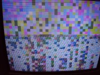
I had great expectations, but now unfortunately, when powering it on, it always shows pulsating random colored blocks, even without a cart... (╥﹏╥)

To be honest, the other day I didn't checked for shorts on the replaced NEO-BUF and guess what, B0 B1 and B2 appear to be shorted, it's the side near the dip switches. I'm wondering how the other day it could reach the cross hatch screen but not now? (wild guess I would say the video RAM's check is at the beginning of the boot sequence)

Anyway, back to fix the NEO-BUF...
 

Attachments

  • random-blocks.jpg
    random-blocks.jpg
    118.5 KB · Views: 40
If that pin was loose there could be others, which maybe causing the watchdog. I would check them all (on all the surface mount chips). You could also power on the board while applying downward pressure on one of the surface mount chips (trying this on each of them) to see if get a behavior change/crosshatch. This can sometimes direct you to the chip or area of a board that has a loose connection.
 
Good news everyone, a colleague revised some of the soldering on the NEO-BUF repro — the castellated holes were not easy to solder — and now the board boots!

٩(^ᗜ^ )و ´-

Big thanks to @ack, @channelmaniac, @ShootTheCore and @Neo-Alec for all the tips, without you guys I wouldn't have been able to pull it off.
 

Attachments

  • booting.jpg
    booting.jpg
    93.9 KB · Views: 26
Last edited:
Back
Top