Big_P Big_p
Professional
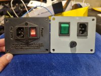
It ends up looking like this...
The big power cap goes from a cheap chinese 470uf 200v to a 560uf 250v Nishicon long life.
Looking at the rectifier diodes I am not interested in playing the game of what blows first, your 2A fuse or your 2A diodes. Out they come, holes ever so slightly drilled out, if you are careful you shouldn't have to scratch back too much mask to get a good solder.
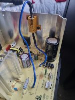
The 140ohm white wire wound is a key point of failure in these chassis (along with almost every cap). These have been specked at 140ohm 25W to assist in heat dissipation of the transistor mounted on the back wall. If we cool this transistor a little better we can get this specked right 180ohm 25W, an ali clad mounted to the back wall does nicely.
While we are here we will replace the cap after the transistor with another Nishicon long life taking it from 100uf @ 160v to 150uf @ 250v
The trimpot in this area adjusts the DC Voltage which should read 110v over the 2w grey resistor to the bottom left (which the ali wall up) of the old white 140ohm wire wound. If you are using a 240v to 120v step down transformer to power this thing you likely have 117v comming in adjust it back to read 110v DC over the resistor.
This thing should be a little more reliable now. Still a few more things to change out (all the caps) but that can wait a bit.
The big power cap goes from a cheap chinese 470uf 200v to a 560uf 250v Nishicon long life.
Looking at the rectifier diodes I am not interested in playing the game of what blows first, your 2A fuse or your 2A diodes. Out they come, holes ever so slightly drilled out, if you are careful you shouldn't have to scratch back too much mask to get a good solder.
The 140ohm white wire wound is a key point of failure in these chassis (along with almost every cap). These have been specked at 140ohm 25W to assist in heat dissipation of the transistor mounted on the back wall. If we cool this transistor a little better we can get this specked right 180ohm 25W, an ali clad mounted to the back wall does nicely.
While we are here we will replace the cap after the transistor with another Nishicon long life taking it from 100uf @ 160v to 150uf @ 250v
The trimpot in this area adjusts the DC Voltage which should read 110v over the 2w grey resistor to the bottom left (which the ali wall up) of the old white 140ohm wire wound. If you are using a 240v to 120v step down transformer to power this thing you likely have 117v comming in adjust it back to read 110v DC over the resistor.
This thing should be a little more reliable now. Still a few more things to change out (all the caps) but that can wait a bit.
Attachments


Last edited: